
Kinugawa Turbo Systems Architecture: Take Mazdaspeed 3 MZR DISI 2.3 L Turbo For An Example
1. Introduction: The Intersection of Legacy Performance and Modern Aerodynamics
The automotive performance landscape is currently witnessing a renaissance of platform-specific engineering, particularly for turbocharged vehicles from the mid-2000s that defined the "hot hatch" era. Among these, the Mazdaspeed 3 (and its all-wheel-drive sibling, the Mazdaspeed 6) stands as a paragon of raw, mechanical engagement. Powered by the MZR 2.3L DISI (Direct Injection Spark Ignition) engine, this platform introduced direct injection to the mass market, pairing high-compression torque with forced induction in a way that challenged the established hierarchy of sport compact performance. However, as these chassis mature and enthusiast goals shift from simple maintenance to high-performance restoration, the limitations of the original equipment manufacturer (OEM) hardware have become the primary bottleneck to reliability and power generation.
This white paper serves as a comprehensive engineering analysis of the induction systems available for the MZR DISI platform, specifically focusing on the transition from the OEM Hitachi/Warner K04 infrastructure to the advanced aerodynamic profiles offered by Kinugawa Turbo Systems. The objective of this document is to move beyond superficial product descriptions and provide a rigorous, data-driven examination of turbocharger fluid dynamics, tribology (bearing sciences), and system integration. By dissecting the physics of the proprietary "STS" (Superior Turbine Strike) technology, the structural advantages of point-milled billet compressor wheels, and the thermal resilience of ceramic ball bearing cartridges, this report establishes a new technical baseline for the Mazdaspeed community.
2. The Thermodynamic Baseline: Deconstructing the OEM K04-882
To appreciate the engineering advancements inherent in the Kinugawa TD-series application, one must first conduct a forensic analysis of the incumbent technology. The factory-installed turbocharger on the Mazdaspeed 3 is a K04 variant, specifically the K0422-881 or K0422-882, manufactured by Hitachi under license from BorgWarner. While this unit was sufficient for the stock output targets of approximately 263 brake horsepower (BHP) and the responsiveness required for daily driving, it represents a significant restriction for any enthusiast targeting wheel horsepower (WHP) figures in the 300 to 400 range.
2.1 Geometric Limitations and Volumetric Efficiency
The fundamental limitation of the OEM K04 lies in its physical dimensions and the resulting aerodynamic choke points. The K04 employs a cast aluminum compressor wheel with an inducer diameter of approximately 45.0mm and an exducer diameter of 56.25mm. On the exhaust side, the turbine wheel utilizes a standard 12-blade cast Inconel design with an inducer of roughly 50.1mm and an exducer of 44.5mm. These dimensions define the turbocharger's "choke line"—the point at which the compressor can no longer supply the air mass required by the engine without generating excessive heat or hitting sonic speeds at the blade tips.
For a 2.3L engine, which has a relatively large displacement for a four-cylinder of its era, these wheel sizes act as a restrictor plate at high rotational speeds. As engine RPM climbs past 5,500, the volumetric efficiency (VE) of the K04 plummets. The small turbine wheel and tight turbine housing Area/Radius (A/R) ratio create excessive Exhaust Manifold Absolute Pressure (EMAP). This backpressure is not merely a parasitic loss; it creates a reversion effect where hot exhaust gases are trapped in the combustion chamber during the valve overlap period.
 Which Turbine Housing A/R Works Best?
This retention of exhaust gas dilutes the incoming fresh air-fuel charge and raises the cylinder's internal temperature. In a direct-injection engine like the MZR DISI, which is already knock-sensitive due to its high static compression ratio, this added thermal stress drastically lowers the detonation threshold. The Engine Control Unit (ECU) responds by pulling ignition timing (Knock Retard), resulting in the characteristic power "drop-off" felt by Mazdaspeed owners near the redline. The engineering consensus is clear: to unlock the engine's potential, the ratio of exhaust backpressure to boost pressure (EMAP:IMAP) must be improved, necessitating a move to a larger, more efficient turbine stage.
2.2 Mechanical Failure Modes: The Thrust Bearing Crisis
Beyond aerodynamic limitations, the OEM K04 suffers from a widely documented mechanical vulnerability: the thrust bearing assembly. The stock turbocharger utilizes a standard journal bearing system with a 270-degree thrust bearing pad. The thrust bearing is responsible for managing the axial loads generated by the pressure differential between the compressor and turbine wheels.
In a stock application, this design is adequate. However, when enthusiasts increase boost pressure through tuning—often pushing the K04 to 21 PSI or higher—the axial load increases exponentially. The 270-degree pad does not support the shaft around its entire circumference, leading to uneven load distribution during rapid transient boost events. Over time, this causes the oil film supporting the shaft to break down (boundary lubrication regime), resulting in metal-on-metal contact.

This failure mode manifests as excessive shaft play, which eventually compromises the dynamic oil seals on the turbine side. Once the seal integrity is breached, pressurized oil leaks directly into the hot turbine housing, creating the thick blue/white smoke at idle that has become the hallmark of a failing K04. Market research indicates that many owners facing this failure consider rebuilding the unit or replacing it with another OEM turbo. This approach is fundamentally flawed, as it merely reintroduces the same structural weakness back into the vehicle's ecosystem. The Kinugawa solution, by contrast, focuses on structural evolution, replacing the K04 architecture with the more robust Mitsubishi-derived TD05 and TD06 frames.
3. The Kinugawa Frame Evolution: TD05H, TD06SL2, and TF06
The Kinugawa strategy for the Mazdaspeed platform is defined by a shift in geometric philosophy. Rather than attempting to optimize the undersized K04 frame, Kinugawa adapts the TD05 and TD06 bearing housings and wheel profiles—architectures originally proven in the Mitsubishi Lancer Evolution and Subaru WRX STI markets—to fit the Mazda footprint. This "Bolt-On" approach retains compatibility with the stock exhaust manifold and downpipe flanges while fundamentally altering the engine's breathing characteristics.
3.1 The Street Performance Standard: TD05H-18G
For the majority of Mazdaspeed owners, characterized as the "Street/Strip" demographic seeking 300 to 400 WHP, the TD05H-18G represents the optimal balance of transient response and mass flow capacity.

Kinugawa Turbo TD05H-18G for MAZDA Mazdaspeed 3 6 MPS MZR DISI 2.3L CX7 CX9
Price: $989.00 USD
Great upgrade for 400whp with excellent throttle response. Perfect for street and track duties. Fits 2007-2013 Mazdaspeed 3/6/CX7/CX9.
Buy Now - $989.003.1.1 Compressor Aerodynamics: The 18G Profile
The Kinugawa 18G compressor wheel features a 50.3mm inducer and a 68.0mm exducer. Comparing this to the OEM K04 (45mm/56mm) reveals a massive increase in the wheel's physical capacity to move air. The 18G wheel utilizes a 12% larger inducer area and a 21% larger exducer diameter.
Crucially, Kinugawa employs billet aluminum construction for these wheels. Traditional cast wheels are limited by the manufacturing process, which requires thicker blades and larger hubs to maintain structural integrity during the cooling phase of the casting process. Billet wheels, machined from a single block of forged aluminum, allow for significantly thinner blade profiles and smaller hub diameters. This has two profound engineering effects:
Increased Blade Surface Area: Thinner blades with smaller hub diameters maximize the effective flow area within the compressor housing, allowing the wheel to grab more air per revolution.
Reduced Moment of Inertia: Despite being physically larger than the cast K04 wheel, the billet 18G wheel maintains a competitive rotational mass. This reduction in inertia () minimizes the energy required to accelerate the wheel, preserving the low-end throttle response that Mazdaspeed owners prize.
 Why is the splitter blade (6+6) better for the low-end torque?
3.1.2 Turbine Dynamics: The TD05H Advantage
The turbine side is where the battle against backpressure is won. The TD05H turbine wheel measures 56.0mm at the inducer and 49.2mm at the exducer. This sizing is strategically selected to open up the exhaust path. The larger exducer (49.2mm vs. the OEM 44.5mm) increases the flow area at the turbine exit, drastically reducing EMAP.
By lowering the pressure differential across the engine, the TD05H turbine improves cylinder scavenging. This allows the engine to operate more efficiently at high RPM (6,000+), where the K04 would typically choke. The result is a power curve that pulls hard to the redline rather than falling off, extending the usable powerband of the vehicle.
3.2 The Mid-Range Punch Solution: TD05H-20G
For enthusiasts targeting the 450 to 500+ WHP range, often involving built engines with forged internals, the we identifies the TD05H-20G as the "Mid-Range" solution.

Kinugawa Turbo 3" TD05H-20G for MAZDA Mazdaspeed 3 6 MPS MZR DISI 2.3L CX7 CX9
Price: $899.00 USD
Great upgrade for more power with excellent mid-range to high-range response. Fits 2007-2013 Mazdaspeed 3/6/CX7/CX9. Features 3" inlet and anti-surge compressor housing.
Buy Now - $899.003.2.1 The 20G Compressor and Surge Mitigation
The 20G compressor wheel steps up to a 52.3mm inducer and a 68.0mm exducer. This wheel profile pushes the efficiency islands of the compressor map further to the right and upward, supporting higher pressure ratios (25-30 PSI) without superheating the intake charge. This capacity is essential for maximizing the density of the air charge in high-boost applications.
However, high-flow compressors on relatively small displacement engines can be prone to compressor surge at low RPMs. Surge occurs when the engine cannot ingest the volume of air the turbo is producing, causing the airflow to reverse and "chop" against the compressor blades. To mitigate this, Kinugawa equips the TD05H-20G with a 3" Anti-Surge (Ported Shroud) compressor cover. This housing features recirculation slots machined into the inlet, allowing excess air to bleed back into the intake stream during surge conditions. This stabilizes the airflow, protecting the bearing assembly from damaging axial shock loads and widening the surge margin of the turbocharger.
 How does the anti-surge compressor housing work?
3.3 The Track Dominator: TF06-18K
A critical differentiator for Kinugawa in the aftermarket landscape is the proprietary STS (Superior Turbine Strike) technology. While standard Mitsubishi-style turbines typically use 11 or 12 blades, Kinugawa’s STS wheels utilize a 9-blade geometry. This is not an aesthetic choice; it is a calculation of fluid dynamics and physics.

Kinugawa Turbo Ball Bearing 4" TF06-18K for MAZDA Mazdaspeed 3 6 MPS MZR DISI 2.3L CX7 CX9
Price: $1,539.00 USD
High-performance ball bearing turbo capable of 450+whp. Features 4" inlet, dual ceramic ball bearing, and billet 7+7 compressor wheel. Fits 2007-2013 Mazdaspeed 3/6/CX7/CX9.
Buy Now - $1,539.003.3.1 The Physics of 9-Blade and 5+5 10 Blade Geometry
Mass Reduction: By removing 2 to 3 blades from the turbine wheel, the total mass of the assembly is reduced. Since the turbine wheel is the heaviest rotating component in the CHRA (Center Housing Rotating Assembly), any weight reduction here has a magnified effect on rotational inertia. Kinugawa data suggests this yields a 5-8% reduction in time-to-boost compared to a standard 12-blade wheel of the same diameter.
Flow Area Expansion: Fewer blades mean less physical blockage in the exhaust throat. This increases the "swallowing capacity" of the turbine, further reducing backpressure. Lower backpressure translates to lower Exhaust Gas Temperatures (EGT) and improved volumetric efficiency.
Efficiency Optimization: While reducing blade count can theoretically lower efficiency at very low flow rates (due to less surface area to capture exhaust energy), the STS design optimizes the blade curvature and loading (aerodynamic lift) to maintain high efficiency across the operational range. This allows a larger turbine wheel (like the TD05H) to spool with the responsiveness of a smaller wheel (like the K04) while flowing significantly more air.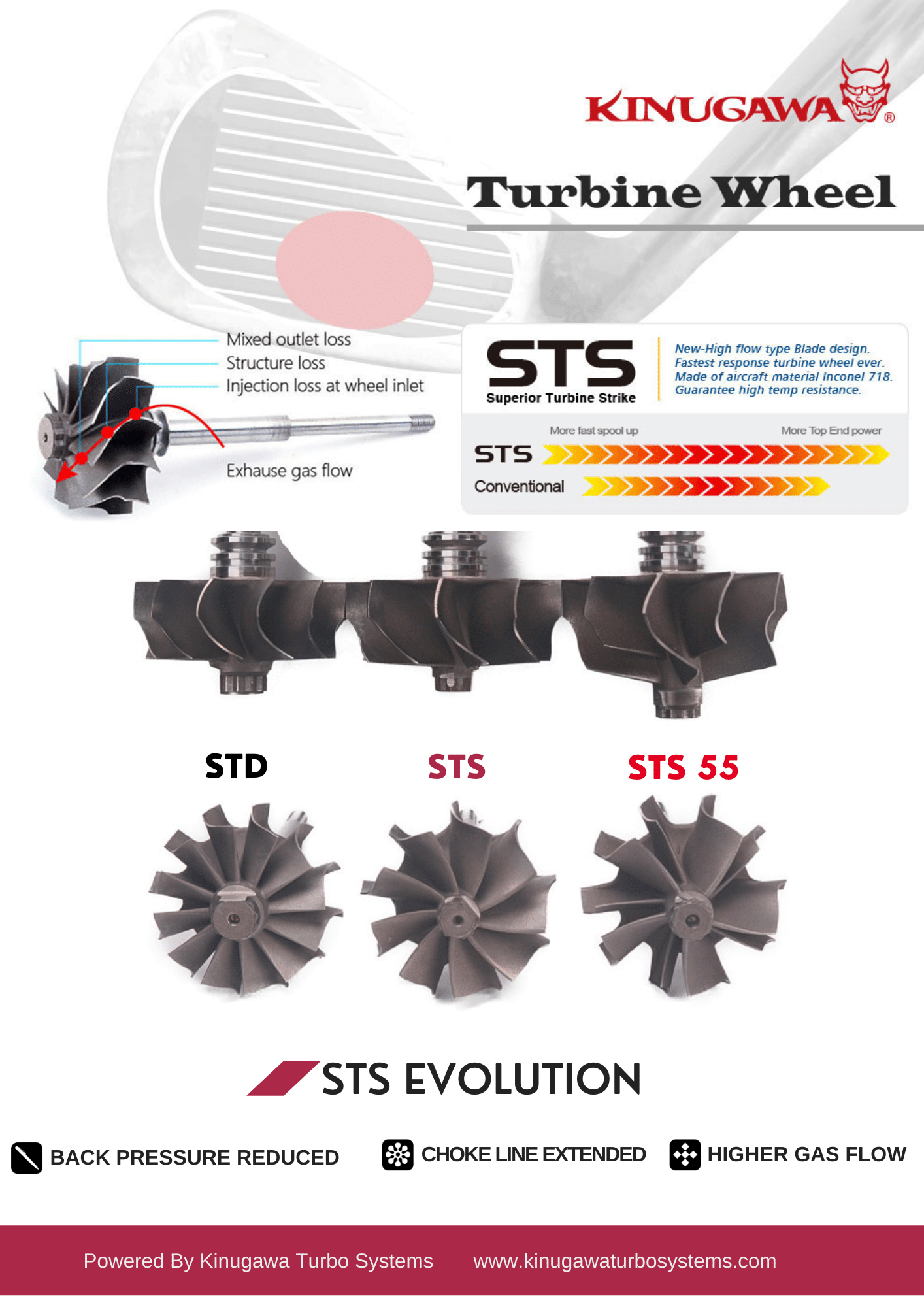
3.4 Bearing Tribology: Defining Reliability
The reliability of a turbocharger is defined by its bearing system—the interface that supports the shaft spinning at over 100,000 RPM. Kinugawa addresses the K04’s Achilles heel (the thrust bearing) with two distinct, robust solutions.
3.4.1 Performance Journal Bearing (The Value Proposition)
Kinugawa’s journal bearing options are significantly upgraded over the OEM standard. They utilize a 360-degree thrust bearing kit. Unlike the OEM 270-degree pad, which leaves a quadrant of the thrust collar unsupported, the 360-degree washer provides full-circle support for axial loads. This doubles the load-carrying capacity of the bearing, making it virtually immune to the thrust failures that plague the stock K04 at high boost levels. This represents the cost-effective, reliable choice for daily drivers who want "set it and forget it" durability.
 Oil Pads Ramping: The Secret to Boosting Performance and Turbo Life
3.4.2 STS Advanced: Dual Ceramic Ball Bearing
For maximum performance, the STS Advanced system employs a dual ceramic ball bearing cartridge.
Friction Reduction: Rolling element bearings generate significantly less friction than hydrodynamic journal bearings, particularly during the initial spool-up phase, where oil pressure dynamics are critical. The reduced drag coefficient allows the turbine to accelerate more rapidly.
Transient Response: This friction reduction improves boost response speed by 10-15%. This is most noticeable during on/off throttle transitions (e.g., gear shifts or corner exits), where the turbo recovers boost pressure almost instantaneously.
Material Science: The use of ceramic balls rather than steel reduces the mass of the rolling elements, further lowering inertia and reducing heat generation. The cartridge design presses the inner race onto the shaft and the outer race into the CHRA, providing precise shaft control and damping against gyroscopic forces.
 Ball Bearing vs. Journal Bearing Turbos
4. System Integration: The Ecosystem of Performance
A turbocharger does not exist in a vacuum; it is the heart of a complex induction and exhaust system. We emphasize viewing the vehicle as a holistic system. Installing a high-flow turbocharger without addressing the supporting ecosystem is a recipe for suboptimal performance or catastrophic engine failure.
4.1 The "Drop-In" vs. "System Upgrade" Distinction
It is crucial to clarify that while Kinugawa turbos are "bolt-on" in terms of physical flange compatibility (fitting the stock exhaust manifold and downpipe), they are "system upgrades" that require a supporting ecosystem. The increased air mass supplied by an 18G, 20G, and 18K turbo exceeds the capacity of several stock components.
4.1.1 Fueling: The HPFP Imperative
The MZR DISI fuel system is the primary limiter for horsepower. The stock High Pressure Fuel Pump (HPFP) internals are notorious for their inability to maintain rail pressure as airflow increases past stock levels. Installing a Kinugawa 18G without upgrading the HPFP internals is a critical error. The increased air density will demand more fuel than the stock pump can deliver, causing fuel pressure to drop. This leads to a lean air/fuel mixture, which under big boost will almost instantly result in detonation and engine destruction. Upgraded HPFP internals (such as those from Autotech or CorkSport) are a mandatory prerequisite for any turbo upgrade on this platform.
4.1.2 Engine Management and Tuning
The stock ECU mapping is calibrated for the flow characteristics of the K04. It cannot account for the massive increase in airflow provided by a TD05H-18G, TD05H-20G, and TF06-18K. To safely run these turbos, a custom tune is required. This involves using a device like a Cobb Accessport or Versatuner to rescale the Mass Air Flow (MAF) sensor calibrations, adjust load targets, and optimize ignition timing tables for the new efficiency islands of the turbo.
4.1.3 Thermal Management: Intercooling
The stock Top Mount Intercooler (TMIC) is susceptible to heat soak, even with the stock turbo. With the increased mass flow of a Kinugawa unit, the stock TMIC becomes a thermal bottleneck, unable to shed the heat generated by compression efficiently. To maintain consistent power and prevent knock, upgrading to a Front Mount Intercooler (FMIC) or a larger, more efficient Top Mount unit (e.g., with a 3.5" core) is highly recommended.
4.1.4 Exhaust Flow
To maximize the efficiency of the STS turbine wheel, post-turbine backpressure must be minimized. The stock downpipe, with its restrictive catalytic converters, creates significant backpressure. A 3-inch high-flow or catless downpipe is essential to allow the turbine to extract the maximum energy from the exhaust gas and to lower the pressure differential across the turbine wheel.
4.2 Installation Nuances: Oil and Water Management
The longevity of a turbocharger is dictated by the quality of its installation and the management of its fluids. The white paper must address specific installation protocols for Kinugawa units to prevent common post-installation issues like smoking or bearing failure.

4.2.1 Oil Feed and Restriction
Journal Bearing Units: These units rely on a high volume of oil to create the hydrodynamic wedge that supports the shaft. They generally do not require a restrictor unless the engine's oil pressure is excessive (causing oil to push past the seals). Kinugawa recommends using a -4AN feed line with an inner diameter of approximately 0.25 inches to ensure adequate flow.
Ball Bearing Units: Ceramic ball bearings require significantly less oil than journal bearings. In fact, excessive oil pressure can flood the bearing cartridge, causing "skidding" of the balls (instead of rolling) and forcing oil past the dynamic seals. For ball bearing units, an oil restrictor with a 1.0mm to 1.5mm orifice is mandatory to meter the oil flow precisely.
 Does my turbo require an oil restrictor?
4.2.2 Oil Drainage and Orientation
A common cause of "smoking turbo" issues after installation is not a failed seal, but improper drainage. The oil drain line must be vertical, with a deviation of no more than +/- 15 degrees from the vertical axis. Any kinks, restrictions, or "uphill" sections in the drain line will cause oil to back up into the CHRA, flooding the housing and leaking into the exhaust or intake. Ensuring a clean, gravity-fed return path to the oil pan is critical.
 When installing your turbocharger, insure that the turbocharger axis of rotation is parallel to the level ground within +/- 15°. This means that the oil inlet/outlet should be within 15° of being perpendicular to level ground.
4.3 Actuator Setup and Boost Control
The Kinugawa adjustable billet actuator allows for precise boost control tuning. The actuator comes with a default spring (typically 1.0 bar / 14.7 psi). However, the preload setting is critical for proper operation.
- Preload: The actuator rod should be set with 2mm of preload. This ensures the wastegate valve is held tightly shut against the turbine housing seat, preventing exhaust leaks that would delay spool-up.
- Adjustment: Preload is set by adjusting the nuts on the actuator rod. For non-clevis applications, turning the adjustment nut two complete turns (approx. 2mm) achieves the correct tension.
- Spring Customization: Enthusiasts can customize the base boost pressure by swapping springs within the actuator head, though this requires disassembling the actuator canister.
 How to replace the actuator spring and hold the boost pressure as the table described?
5. Benchmarking & Comparative Analysis
To validate the engineering claims, a direct comparison with the OEM baseline and market competitors is required. This data-dense section is critical for winning the "rational" argument in the consumer's mind.
Table 1: Turbocharger Specification Comparison
| Feature |
OEM K04-882 |
|||
| Comp. Inducer | 45.0 mm | 50.3 mm | 52.3 mm | 55.1 mm |
| Comp. Exducer | 56.25 mm | 68.0 mm | 68.0 mm | 75.0 mm |
| Turbine Inducer | 50.1 mm | 56.0 mm | 56.0 mm | 61.5 mm |
| Turbine Exducer | 44.5 mm | 49.2 mm | 49.2 mm | 54.0 mm |
| Blade Tech | Cast 12-Blade | Billet 6+6 / 11+0 | Billet 6+6 / 11+0 | Billet 7+7 (Point-Milling) |
| Turbine Tech | Standard | STS 9-Blade | STS 9-Blade | 9-Blade |
| Bearing | Journal (270°) | Journal (360°) / Ball | Journal / Ball | Journal / Ball |
| Max HP Rating | ~260-280 WHP | 350-400 WHP | 450-500 WHP | ~600 WHP |
6. Conclusion: The Verdict on Engineering Evolution
The transition from the stock K04 to a Kinugawa TD05 or TD06 series turbocharger represents more than a simple repair; it is a fundamental re-engineering of the Mazdaspeed 3’s induction system. By addressing the root causes of the OEM unit's limitations—specifically the exhaust backpressure bottleneck and the weak thrust bearing architecture—Kinugawa unlocks the latent potential of the MZR DISI engine.
Through the application of STS turbine wheels, point-milled billet compressors, and 360-degree or dual ceramic ball bearing systems, Kinugawa provides a solution that is both robust and high-performing. Whether the goal is a responsive 350 WHP street car utilizing the TD05H-18G or a 550+ WHP track weapon built around the TF06-18K, the engineering data confirms that these units provide the airflow mass, thermal management, and mechanical durability required to push the platform into the modern era of performance. For the informed enthusiast, the choice is not based on brand loyalty alone, but on the physics of flow and the reliability of modern materials science.
Appendix A: Glossary of Technical Terms
- CHRA (Center Housing Rotating Assembly): The core of the turbocharger containing the turbine shaft, compressor wheel, and bearing system.
- A/R (Area/Radius): A ratio defining the geometry of the turbine housing. A larger A/R allows for more top-end flow but results in slower spool. A smaller A/R improves spool time but increases backpressure.
- STS (Superior Turbine Strike): Kinugawa’s proprietary 9-blade turbine wheel design, engineered to reduce mass and backpressure.
- Billet Compressor Wheel: A compressor wheel machined from a solid block of forged aluminum (Milled from Solid - MFS), offering a higher strength-to-weight ratio and thinner blade profiles than cast wheels.
- EMAP (Exhaust Manifold Absolute Pressure): The pressure in the exhaust manifold before the turbine. Lower EMAP is critical for volumetric efficiency and knock prevention.
- Point Milling: An advanced machining process used for billet wheels that allows for complex, 3rd-order surface blade curvatures, improving aerodynamic efficiency.
Appendix B: Recommended Supporting Modifications Matrix
- HPFP Internals: Autotech or CorkSport (Essential for all upgrades).
- Engine Management: Cobb Accessport or Versatuner for ECU calibration.
- Downpipe: 3-inch diameter, catless or high-flow catalytic converter.
- Intercooler: Front Mount Intercooler (FMIC) or upgraded Top Mount (3.5" core).
- Intake: 3-inch or larger intake system to match the turbo inlet.
- Boost Control: 3-Port Electronic Boost Control Solenoid (EBCS) for precise boost management.